Our Expertise
- Wooden Patterns and Core Boxes
- Metallic Patterns and Core Boxes
- Impellers
- Prototype Castings
- Processed Products
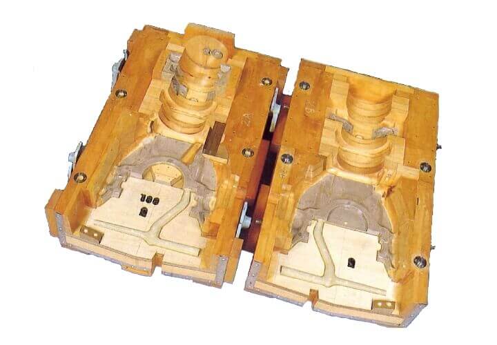
Wooden Patterns and Core Boxes
Wooden Joinery – Technology to prevent dimensional changes in wood
A resin pattern can be manufactured with less than half the weight by using wood. However, dimensional changes may occur. We solve the problem by how we put wooden parts together.
- ・Wood does not shrink in the direction in which the fiber grows, but shrinks in the direction in which the fiber cross at right angles.
Wooden joinery is a technique that considers the direction of the fibers and position wooden parts so as to resist the shrinkage of the wood in order to prevent dimensional changes. - ・In case that the pattern is likely to break, such as an elongated shape, wooden parts should be arranged in the direction in which the fiber can give strength.
- ・In order to improve the useful life and to prevent splinters due to aging, wooden parts are placed considering the angle of the fibers with respect to the shape.
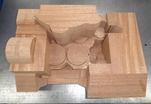
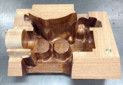
After making the material of the wooden frame, the wooden pattern is made by machining.
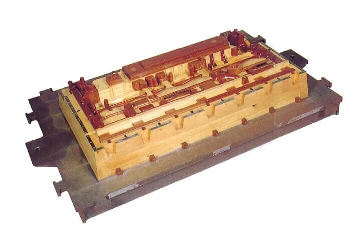
Metallic Patterns and Core Boxes
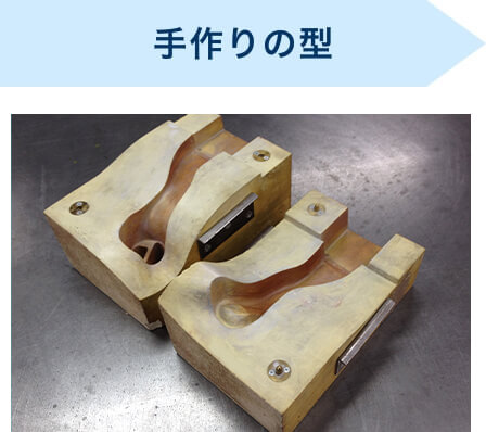
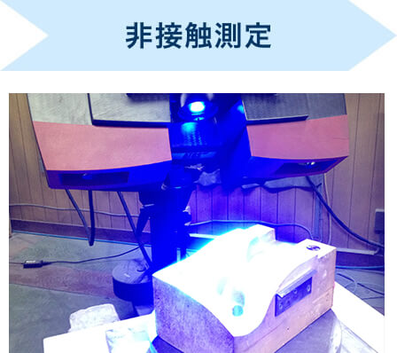
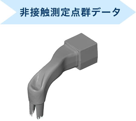
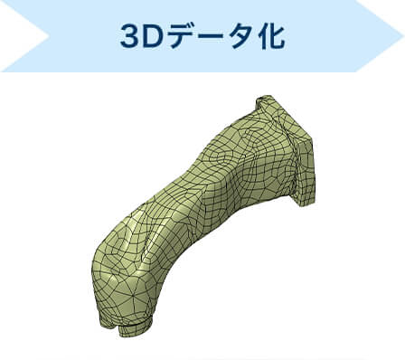
Reverse Modeling (Reverse Engineering)
We measure a pattern without any drawings or data with a non-contact measuring machine (ATOS) and we make it possible for you to have a surface and/or solid model with the measured data.
As long as the shape of the pattern can be measured with a non-contact measuring machine (ATOS), it can be converted into CAD data.
Achievements:
- ・Remanufacturing metallic patterns and/or parts without CAD data.
- ・Digitalizing hand-made prototype into CAD data.
- ・Digitalizing forms that you added molding allowance into CAD data.
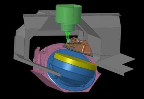
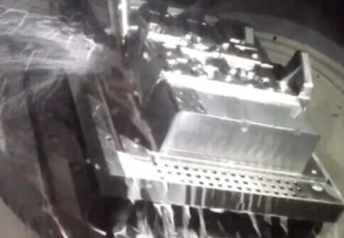
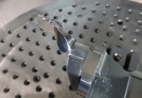
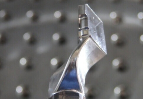
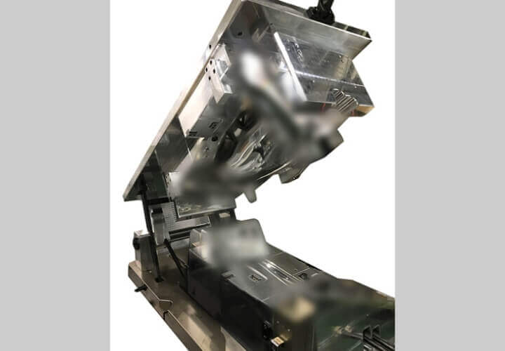
Simultaneous 5-axis Machining
- ・Compared to the work with 3-axis, we are able to process a deeper shape with an excellent machined surface.
- ・Multi-face machining and High-precision processing are available with one setup.
- ・We handle large shapes as Φ1000.
- ・We manage to perform 5-axis machining and turning at the same time so we are able to shorten the machining time thus the delivery time is shortened as well.
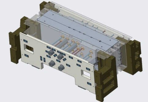
3D Designing
- ・We digitalize our expertise into 3D then design products.
- ・Multiple engineers design products simultaneously.
- ・We make good use of 3D-CAD to design products accurately and quickly.
- ・We use 3D design for simulation and analysis before making a metallic pattern.
- ・We perform shape inspection and assembly inspection using a non-contact 3D measuring machine (ATOS).
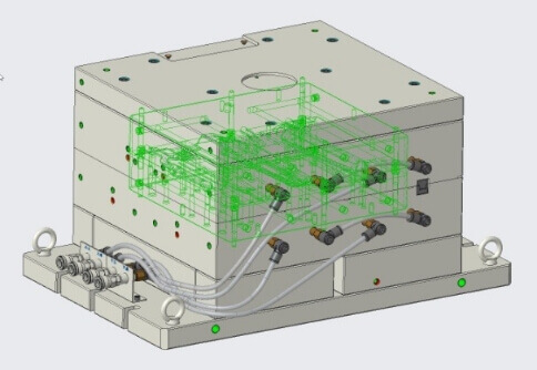
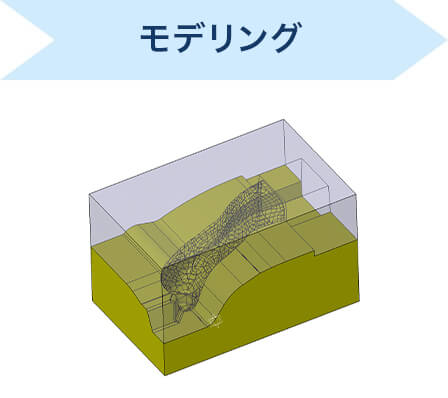
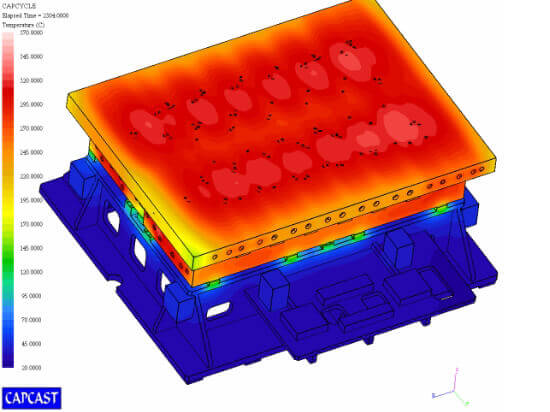
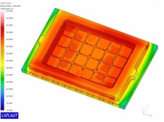
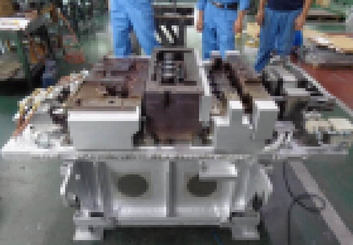
Metallic Patterns Temperature Distribution Analysis
In order to eliminate uneven burning of the core and deformation of the metallic pattern, we verify the appropriate heater arrangement at the time of design. We set the actual molding conditions and perform analysis.
Molding conditions:
- ・Preset temperature
- ・Cycle time -sand blowing, burning, taking out, air blow, etc.
We make a pass/fail judgement by looking at the changes in the colormap as time proceeds. When the design is properly done, the color in the colormap tend to be unified.
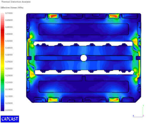
Core Deformation Analysis
Based on the chucking seat of the core, we predict spots where get stressed at the time of removal from the molding machine or of transportation and we comprehend the problems on strength in advance. Based on the result, we enhance strength of the core and also propose the shell thickness.
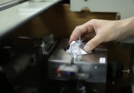
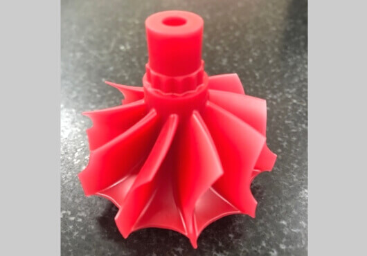
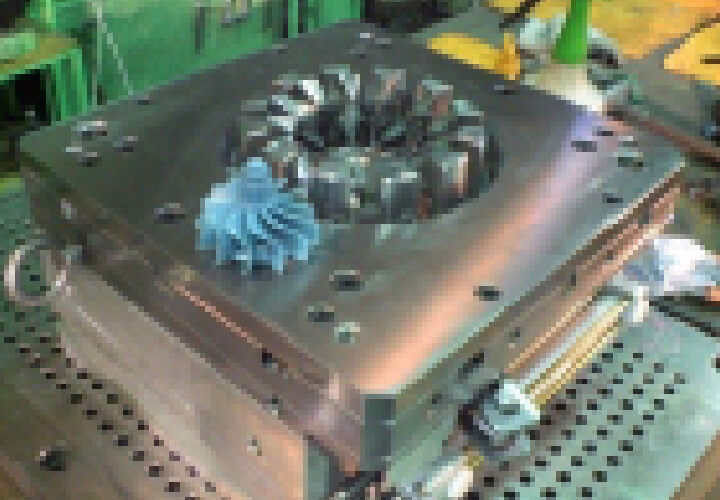
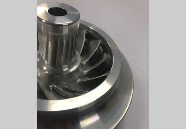
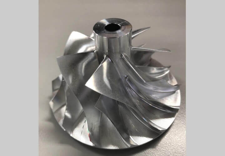
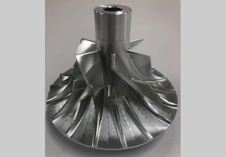
Impellers
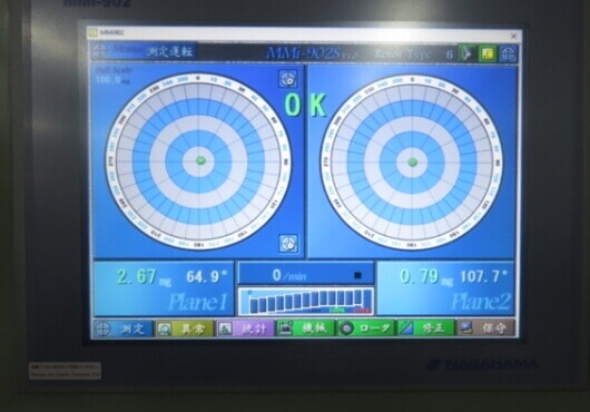
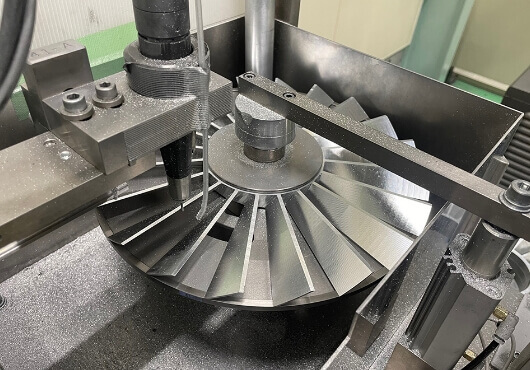
Balancing Measurement and Correction of Impeller
We provide sophisticated balancing. We consistently measure and correct the balance at any point of the process.
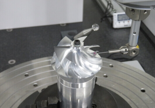
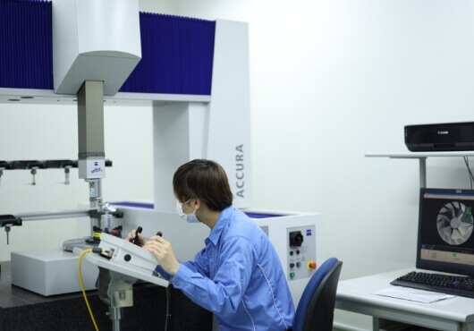
3D Measurement
With the 3D measurement machine, the accuracy of the measurement is higher compare to the result with a non-contact type measurement machine.
We comply with any requests from our customers and guarantee quality.
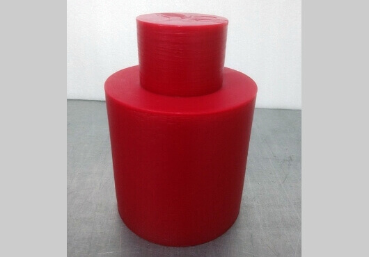
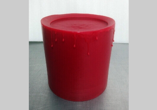
Machinable Wax
- ・We uniquely blend machinable wax which is suitable for casting, has excellent workability and does not easily get deformed even after processing.
- ・The material is molded in our own melting furnace.
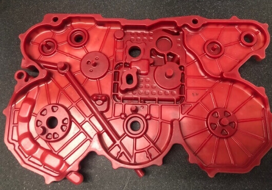
Processing Machinable Wax
We process original blended machinable wax for lost wax precision casting by 5-axis machining.
Prototype Castings
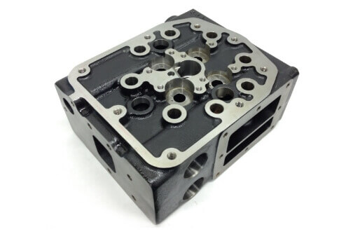
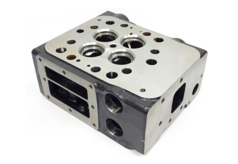
Cylinder Head Made of Nodular Graphite Cast Iron
We receive a request for cylinder head made of nodular graphite cast iron. Unfortunately, after the product shape is confirmed it is difficult to make it.Then how should it be solved?
Actually, it depends on the product shape.
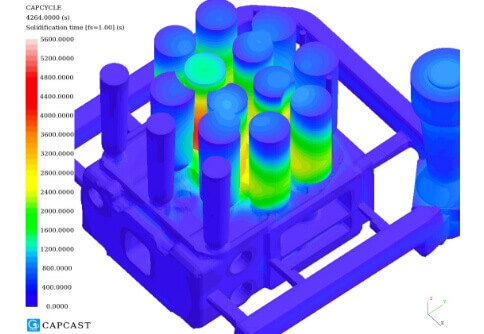
It is necessary to add a lot of cylindrical risers in order to make shrinkage generated during FCD casting out of the product. We aim for directional solidification that the final solidification becomes a riser. When the product has a flat shape to which a riser can be attached, it is highly possible to be manufactured.
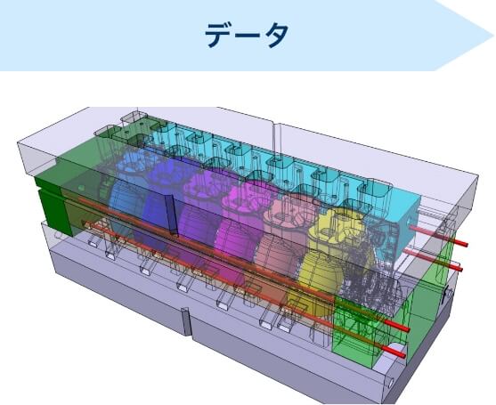
We analyze and simulate the layout of the riser until we get satisfied with the result then cast it.
Because we were able to model the water jacket and the shape of the riser connection freely, we actualized the directional solidification and suppressed the occurrence of shrinkage inside of the product.
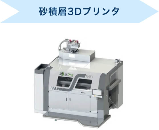
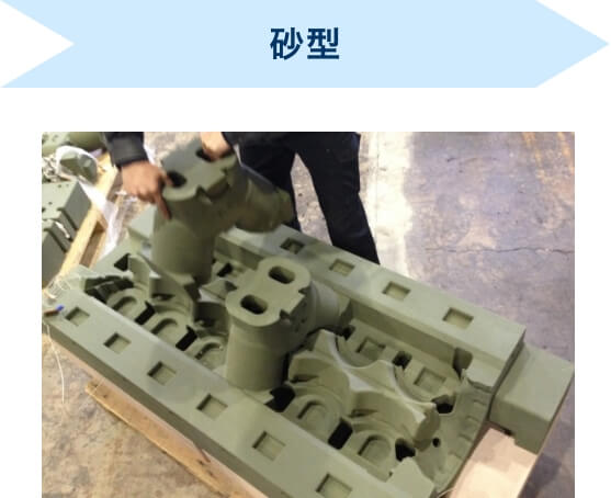
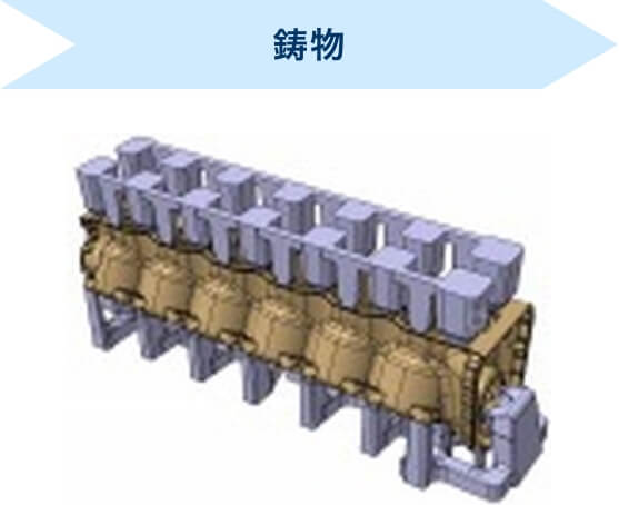
Quick Delivery of Casting by using 3D sand printer
We manufacture castings with short delivery times by using a sand-type laminated 3D printer. (The shortest delivery time: 7 days)
The process can be shortened without “the pattern for sand casting” so that it enables quick delivery. Since you do not have to think about punching with a pattern, you can make castings in any shape.
You can also expect the cost reduction. In most cases, it will be cheaper to make one or two items which do not require any correction with the 3D printer than making a pattern.
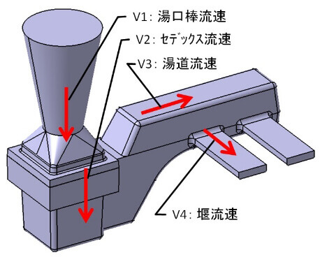
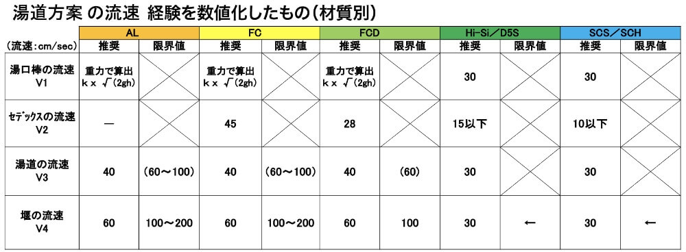
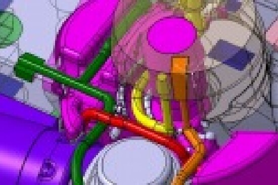
Runner Design – special filter(SEDEX), runner, thickness of weir
When the shape of the product is thin-walled but complex (cylinder head, etc.), we propose a runner design that makes the initial flow velocity of the weir as slow as possible within the target casting time.
On the other hand, when the shape of the product is thick and simple (bracket, etc.), we propose a runner design that makes the flow velocity as fast as possible within the target casting time.
Complex Core Assembly Plan
The following is what we consider when we design the complex core assembly plan.
- ・Position stability when setting the passage core
- ・Retaining of the core grid and the formability
- ・Blow moldability of the form of the core
- ・Taking sand molds out of the pattern
- ・Changing the product shape
We take all the above into consideration then propose to add core prints and/or the division position of the core. Our proposal gives you some ideas of cost reduc
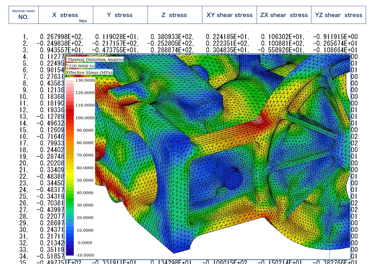
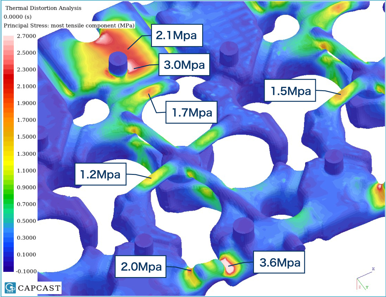
Estimate casting residual stresses in Nastran format.
Casting residual stress analysis values can be estimated in Nastran format. It opens the way for use in the design analysis software that your company uses. Excess thickness of the draft angle, parting edge, dam marks, etc. are analyzed with the accurate casting shape. (If Taguchi Pattern Works made the pattern.)
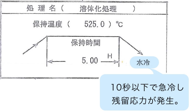
Predict residual stress during quenching after solution treatment.
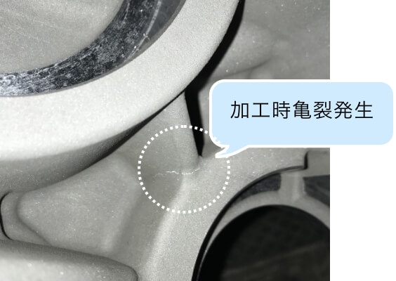
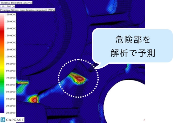
In the heat treatment of aluminum, excessive residual stress may be generated to the product during quenching after solution treatment. It is simply because the material is rapidly cooled with water from a temperature of 500°C or higher.
This may cause cracks so changes in the design shape is required.
We predict a crack risk in advance and it lead to reduce the number of prototypes.
When there is a large difference in wall thickness, excessive residual stress tends to occur.
Can you handle the core?
You can check whether the core has enough strength to handle. This prevents troubles that cannot be cast, such as being damaged when lifted. Contributes to reducing the number of prototypes.
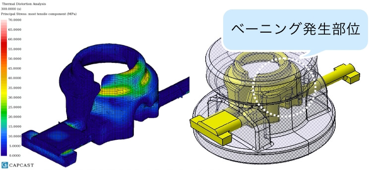
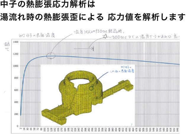
Predict the occurrence of Veining
Because water jacket cores are located inside of the products, once veining occurs, it leads to casting defects.(Water jacket flow channel may get closed.)
To prevent these events, design need to be changed.
We perform thermal expansion stress analysis to predict where the veining occurs. This leads to decreasing the number of prototypes.
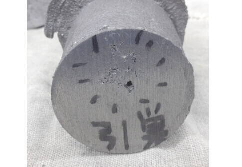
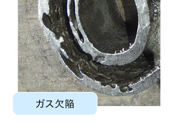
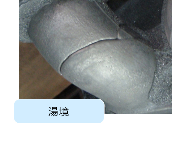
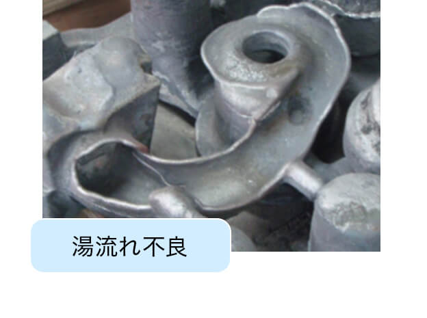
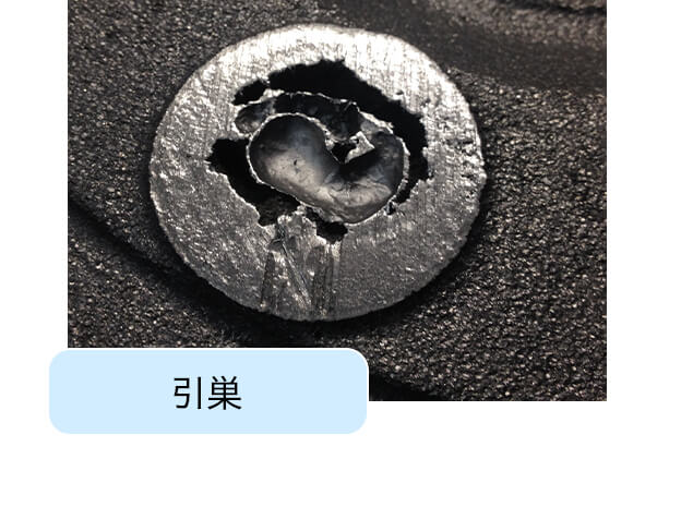
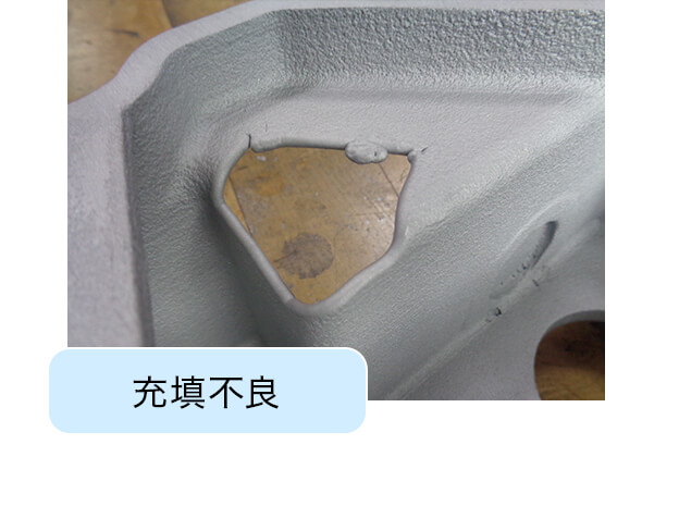
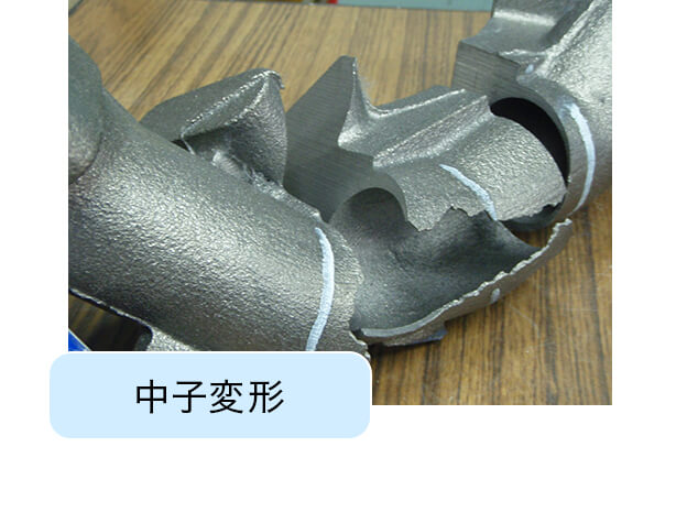
Prototyping learns from failure.
No matter how well you think and prepare, you can still fail. However, failures can lead to limitations of phenomena and new findings.
This is especially true for unprecedented prototypes. Accumulation of considering and recovering from past failures creates the current quality. That’s why we value our failure case database. The figure is an easy-to-understand failure.
Processed Products
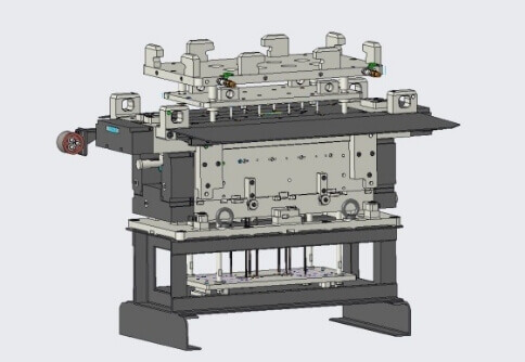
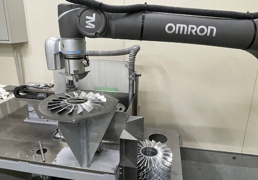
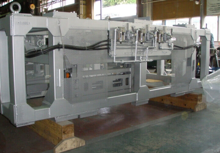
Automatic Deburring Machine
Burr is inevitable during machining. It used to be removed manually in the past but the quantity of work became large, so it is done by robots to reduce cost currently.
Achievements
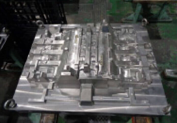
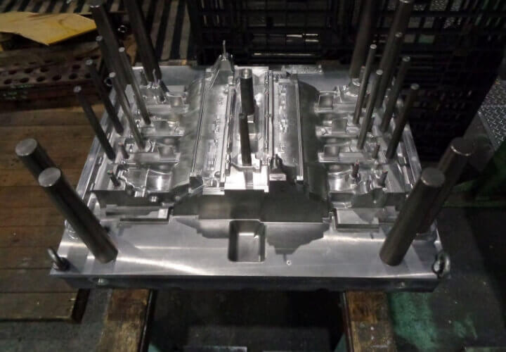
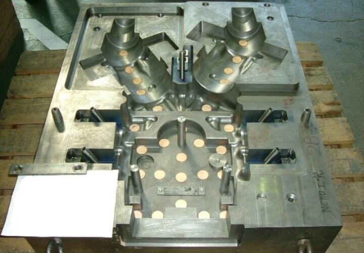
Cylinder Block Water Jacket (Metallic Pattern)
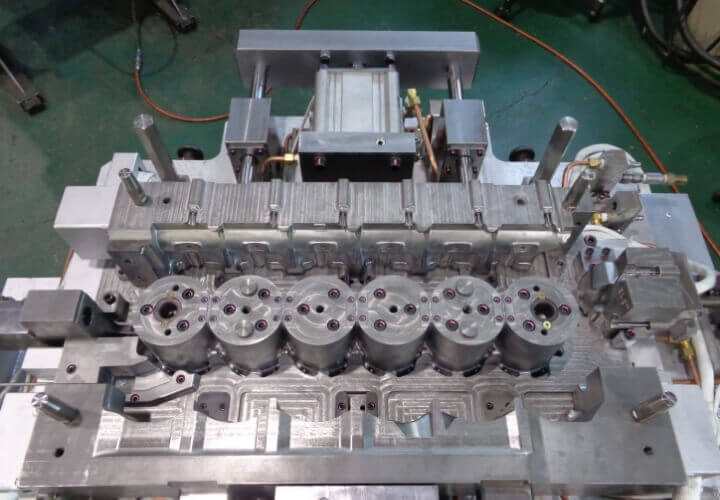
Cylinder Block
(Metallic Pattern with gas pins)
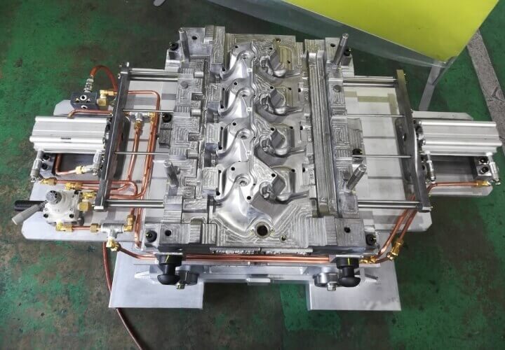
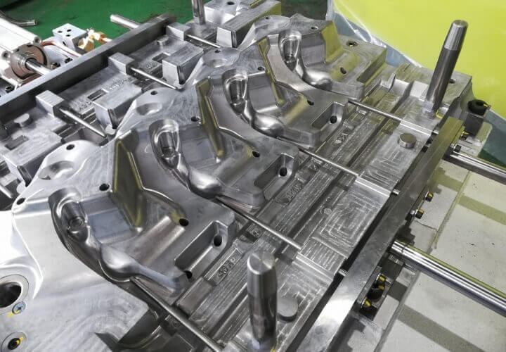
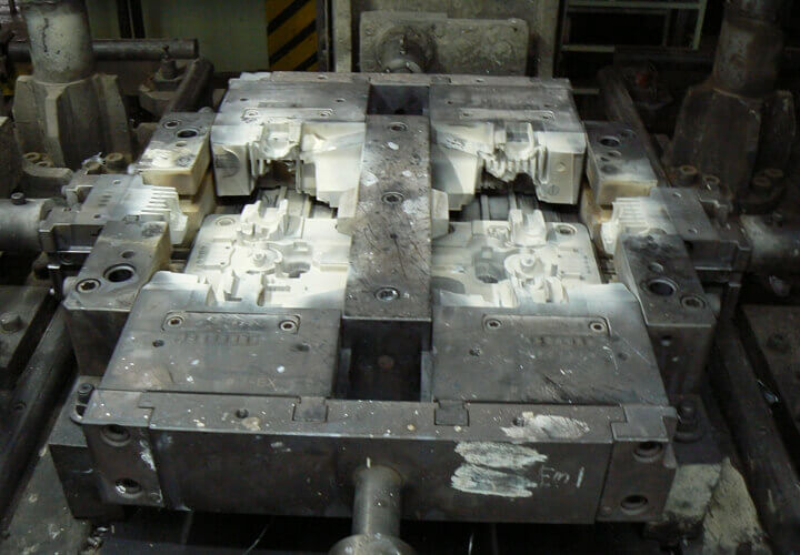
Cylinder Block (3 different cores can be made by only one pattern)
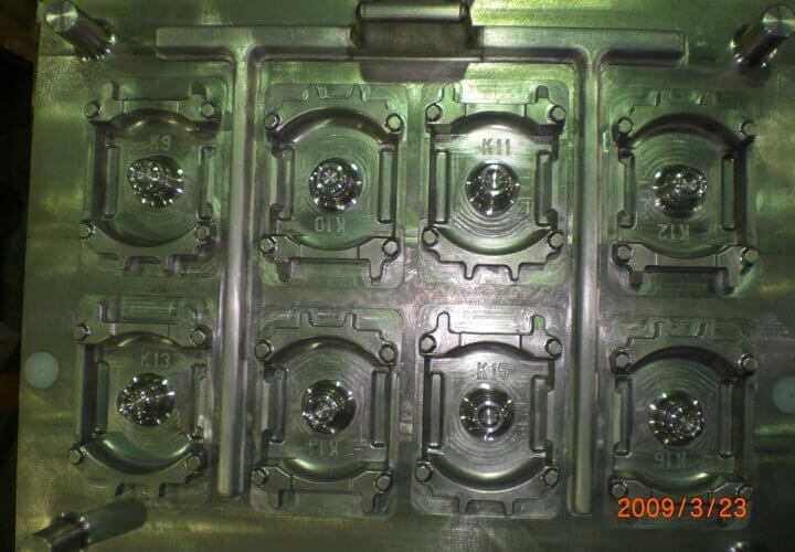
Impeller Wax (Metallic Pattern)
Turbine Blade・Lost-Wax Pattern
Exported to Malaysia Metallic Base Pattern for Casting
Exported to Malaysia Crank Case and Base Pattern for Automobiles
Exported to Malaysia Single Cylinder Head for Motorcycle Low Pressure Die Casting
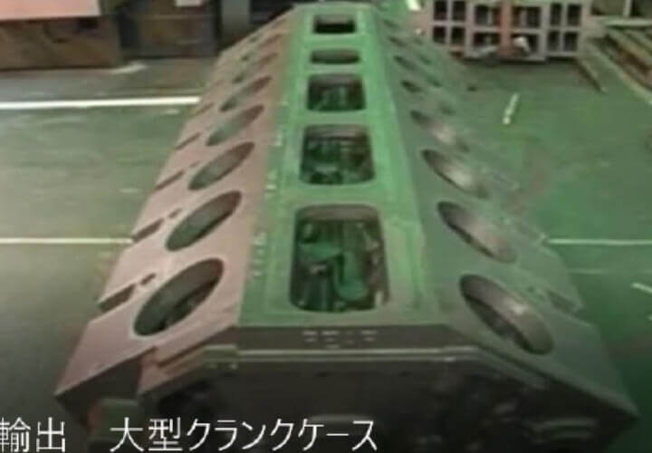
Exported to India Large Crank Case
Exported to India V16 Cylinder Blocks for Generators Metallic Patterns
Exported to India Large Crank Case Metallic Core Boxes
Exported to India Large Crank Case Setting Jig
Exported to India Large Crank Case Machining Jig
Exported to Thailand Metallic Patterns for Automotive Suspension Parts
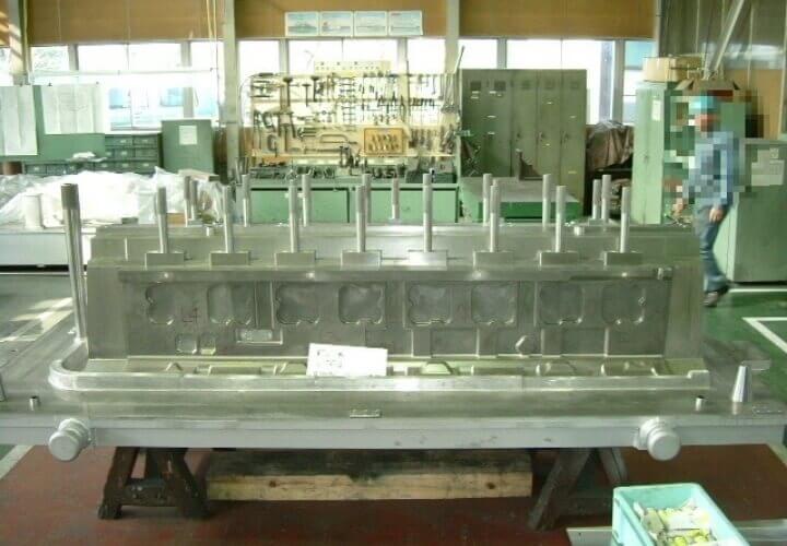
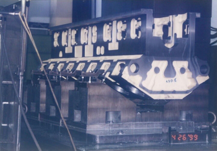
Large Cylinder Block Crank Case Core Boxes
Large Cylinder Block Base Patterns
Shrouded Impellers
Impellers
Multi Spreader Impellers
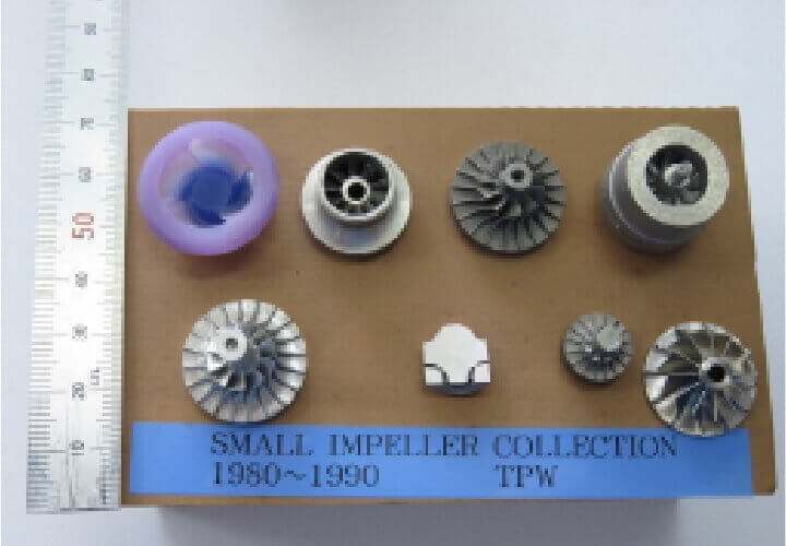
Small Impellers
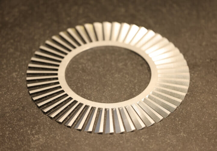
Vacuum pump fixed blades
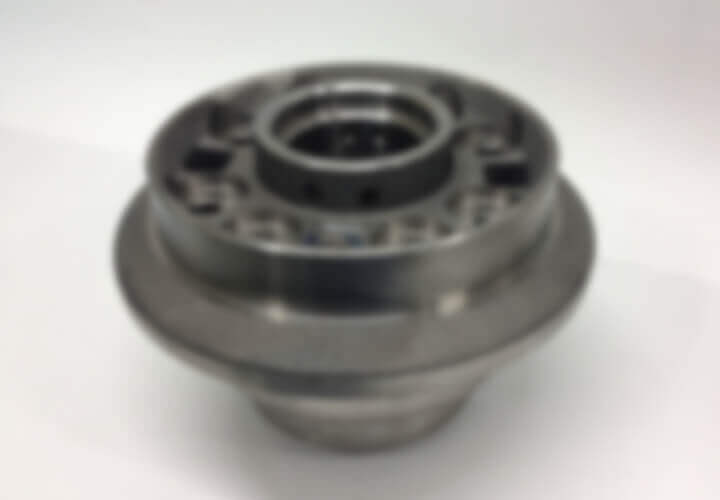
DIFF1
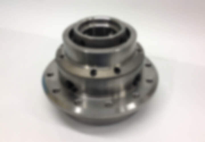
DIFF2
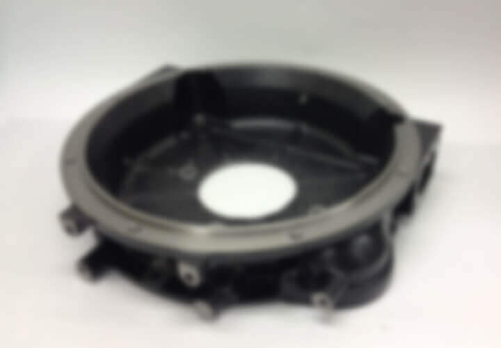
FW_HSG1
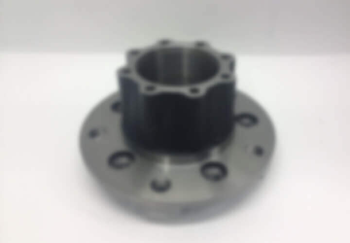
HUB1
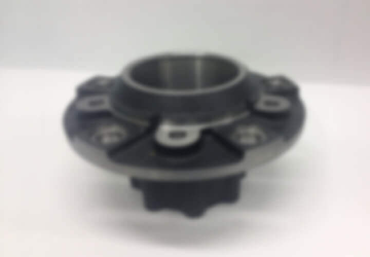
HUB2
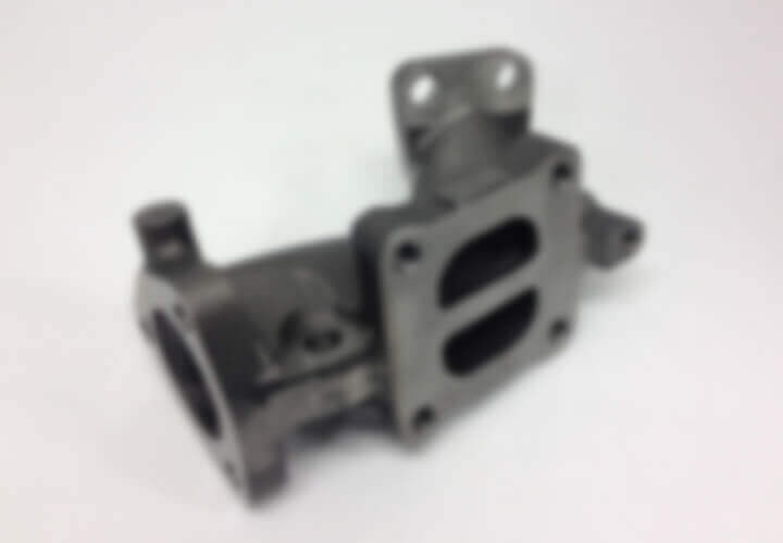
EXHAUST MANIFOLD
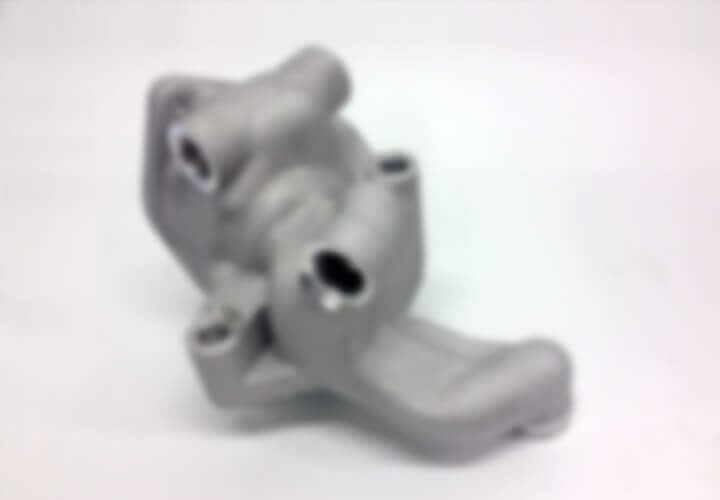
THERMOSTAT HSG1
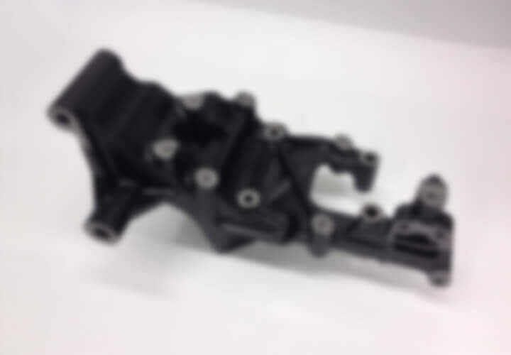
BRACKETS
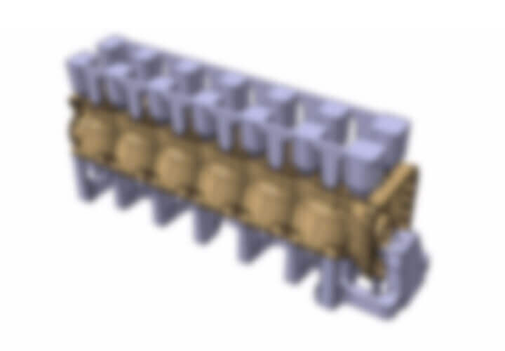
CYLINDER BLOCK
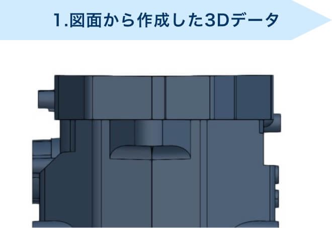
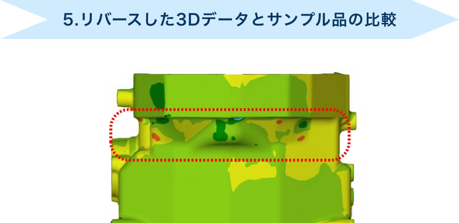
The example of Reverse Modeling
We create 3D data even when you only have the old drawings and sample products left.
- 1. Digitalize 3D data from an old drawing.
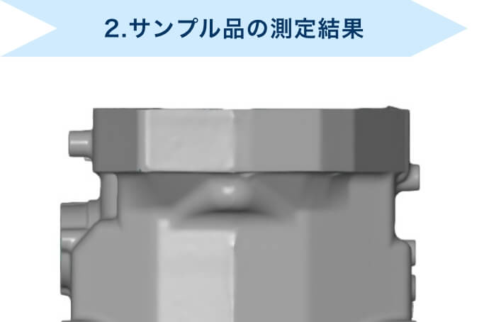
- 2. Measure the sample product with the contact-type measuring machine.
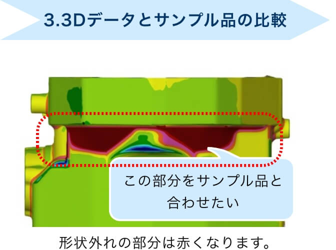
- 3. Compare the 3D data with the measurement result then verify the difference in shape.
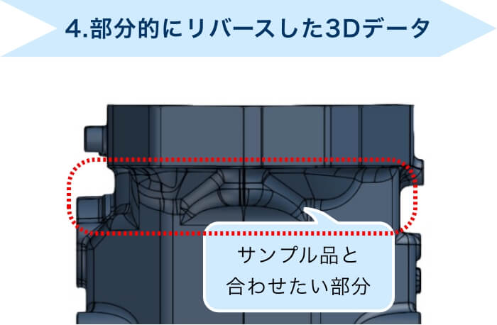
- 4. Ask customers’ opinion about the part(s) they want to match with the sample product then perform reverse modeling accordingly.
- 5. Compare the 3D data from the reverse modeling with the sample product again to confirm the shape.